2017年5月24日 星期三

NodeMcu (1) - Mqtt

By using Lua, it is surprisingly simple to program the NodeMcu (i.e. ESP8266) to connect to a MQTT broker. Here I write a simple lua on NodeMcu, it will
1. connect to a home wifi router
2. connect to a mqtt broker server
3. subscribe to a topic
4. when a message is received, parse the message then turn on/off a LED.

Wifi router

  About the wifi router,  I just use WPA2, an 2.4GHz wifi router.

Mqtt broker

  For the Mqtt broker, you may use "test.mosquitto.org", of course you can setup your own(see my previous post).

Hardware Connection

  The NodeMCU that I use is just a popular one (using CH385 as the USB-to-Uart bridge), make sure you have install the USB-UART driver. Also install the popular nodcmcu development tools ESPlorer.
  I connect a LED to to GPIO0 (marked as D0 on PCB), a 100ohm resistor is used to limit the current draw from GPIO pin. According to the ESP8266 datasheet, the maximum GPIO output current is only 12mA, if no resistor is used, just connect a LED to GPIO and ground directly, I'm afraid it may damage the GPIO, I haven't try, I also don't suggest your try...
   Anyway, see the connection picture below, quite simple.


Source code

  The code is quite strange forward, it will do the following
  1. Setup the wifi as station mode and connect the the router
  2. Repeat to get IP until a valid IP is obtained.
  3. Connect to the Mqtt broker (test.mosquitto.org)
  4. Once the Mqtt broker is connected, subscribed to the topic "wing"
  5. Every time a message is received, then parse the message. If the first character of the message is "0", then set the GPIO0 to low, otherwise set to high. (so as to turn on/off a LED)

wifi.setmode(wifi.STATION)
wifi.sta.config("YOUR_SSID","YOUR_PASSWORD")
wifi.sta.connect()

tmr.alarm(0, 1000, 1, function()
if wifi.sta.getip() == nil then
    print("Connecting")
else 
    print('ip:',wifi.sta.getip())
    tmr.stop(0)
end
end)

print ("start mqtt")
m = mqtt.Client("wingtest",120,"","",1)
m:connect("test.mosquitto.org", "1883", 0)

m:on("connect", function(con) print ("connected") 
    m:subscribe("wing",0)
end)

m:on("offline", function(con) print ("offline") end)

m:on("message", function(conn, topic, data)
    print (topic .. ":")
    print("message=>", data)
    print (string.byte(data,1))
--    print (string.byte(data,2))

    pin=0
    gpio.mode(pin, gpio.OUTPUT)

    if string.byte(data,1) == 48 then
        print ("LOW")
        gpio.write(pin, gpio.LOW)
    else    
        print ("HIGH")
        gpio.write(pin, gpio.HIGH)
    end
end)
 

2017年5月2日 星期二

Node-Red (2) - MQTT testing

What I really want to do is connecting different MCU to the node-red, before I connect a real hardware, I have to test mqtt on node-red first. Without a real hardware, I can just publish a message from the command prompt (using mosquitto_pub) , and see the result at the node-red debug panel.
In this experiment, I use the public Mosquitto MQTT test server, but you can also follow my previous post to setup your own MQTT server.

Run node-red !

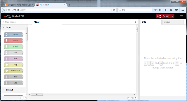
Run node-red , then you can see the following UI in your browser


Drag "mqtt" node from the Left-Hand-Side (under input category) and drop to the Flow 1 area.

Similarly, drag and drop the "debug" node to the Flow 1 area.


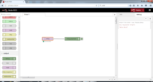
While you moving your mouse inside the Flow 1 area, it is actually in the "wire mode", you can just move the  "cross" (i.e. mouse cursor) to connect a wire from mqtt node to the debug node. (you click on the right square of the mqtt node and drag a line to the left square of the debug node.)

 Then we have to configure the nodes, in this simple flow, only mqtt node is need to be configure. Just double click at mqtt node, and you will see

Then click the pencil at the end of "server",  and you will see the sever input diaglog

You only need to need to enter the server name  "test.mosquitto.org", then click Add on the top. It will then go back to the previous dialog. Now you can enter the topic "wing" (you can change to any other string). Finally press Done button on the top.

Now the Flow is finish creating, we can just press "Deploy" (on the top right) to start the flow.
You can see the mqtt node show status "connected"

You can also check the command prompt (where you run the node-red), it will show some debug information message, such as connected to test.mosquitto.org


To test the Flow, we can publish a message to the topic "wing" at the test.mosquitto.org server.  You can open a command prompt at Windows, and run the following command


-h is the server name
-t is the topic
-m is the message you are going to publish

Then at the node-red UI, you should see a received message at the debug area (right hand side).

Node-Red (1) - Installation

We heard the term "IoT" for years, when people talking about IoT, MQTT and Node-red are usually mentioned. It seem Node-red is a user-friendly tools, so I start to evaluate. The first step is, of course, install the node-red.


Installation of node-red for windows

1.  Download node.js windows 64bit version from here . The latest version that I used is v6.10.2 LTS. The Windows that I used is Win 7 64-bit, CPU is i3.

2. Double click to run the file node-v6.10.2-x64.msi , just press next for each screen to finish the installation.

3. After node.js is install successfully, there will be a new item "Node.js" in the start menu. Click the "Node.js command prompt" inside the "Node.js", and you will see a cmd prompt like this

4. In the "Node.js command prompt", enter the following command, then it will install node-red.


5. After the installation finish, type "node-red" to run.

6. Then in browser, enter the link "127.0.0.1:1880" and you can see the node-red UI.


Install MQTT for Linux - using docker

Docker is very popular nowaday, so instead of installing MQTT broker directly on Linux, I try to find if there are any MQTT docker image. It's great that there is an official Mosquitto implementation of MQTT broker by Eclipse. Here are the procedure to install and test these Mosquitto-MQTT broker for Linux.

Linux server

    I'm running and Ubuntu 16.04.2 - 64 bit virtual machine on Digital Ocean, but I think the setup procedure should be the same on a real Linux machine.  I originally run a 32bit version ubuntu VM, but docker only support 64bit version, so I destroy the previous one and create a new 64bit version.

Install Docker

  The first step is , of course, to install the Docker. I use "curl" to install, so install curl first,


Then install docker


You also need to add your user to docker group


The following command will download the eclipse-mosquitto image then create a container (that also mean running the mosquitto services)
web sites for the eclipse-mosquitto https://hub.docker.com/_/eclipse-mosquitto/


see the result


2013年11月24日 星期日

Robot Arm + Arduino + Chrome App


Control Robot Arm using Chrome App and Arduino.

  我先從最簡單的軟體(Chrome App) 和 韌體(Arduino) 開始, 去控制有五個 Servo 馬達的機械手臂. 我會一點點的去修改。現在的階段,動作看起來是有點不順暢連續.

   Based on previous Chrome App to servo demo. I modify a little bit to control 5 servo motors. Then it's time to give the robot arm "life". All the parts of the robot arm are bought from mainland China. I assemble many months ago, I also write a console mode Python program under linux to "talk" to Arduino in order to control the robot arm, then I think I really need a GUI. When I start writing Chrome App, the first thing I want to do is controlling that robot arm.
   Well, I want to see it "move" as soon as possible before I spend too much time for the design of the communication protocol or even algorithms, so I start everything as simple as possible.
   In order to be simplest, a two-byte-protocol is used, that is, only two bytes is sent from Chrome App to Arduino (through Serial API) everytime.The first byte is the Id of the servo motor, second byte is the position. The range of position of each servo motor is only 10, so I only need to send character 0 to 9, and in the Arduino, it can be converted to integer easily. In Arudino, there is a simple switch-case to determine which servo motor to be controlled.
  There are a lot to be modified, the first thing is the protocol, may be I will also modified the mechanical part because I think the arm is "too short".

You can find the source code of the Chrome App and Arduino in here.
https://github.com/winghackerspace/chromeapp_sample/tree/master/arduino_robotarm

A short demo video


The electronics parts is just and Arduino UNO with a sensor shield, no extra hardware.

2013年10月27日 星期日

Chrome App (3) - Arduino Servo Motor

RCサーボモータをArduinoとChromeAppで制御
Chrome App to control Arduino Servo Motor
以Chrome App 控制 Arduino 伺服馬達

From Google ChromeApp samples, there is a servo motor.sample code. So I base on that sample, and modify a little bit to my previous Arduino-test-led demo.
  In this demo,  you can just use the slider in the Chrome App to control the servo motor attached to the Arduino. In order to make the code simpler, the range of the slider is only 10(0 to 9). Whenever you change the slider, a character of '0' to '9' will be sent to Arduino.
  This is a rather simple demo, but it is the preparation to my next small project. Hopefully it will make you feel more interesting.

Here you can find my source code for both Chrome App and Arduino.
https://github.com/winghackerspace/chromeapp_sample/tree/master/arduino_test_servo

The reference Chrome-app-samples is
https://github.com/GoogleChrome/chrome-app-samples/tree/master/servo


2013年10月26日 星期六

Chrome App (2) - Microchip USB

Use Chrome App to control Microchip PIC18 through USB interface.
Chrome App から Microchip PIC18を制御
以Chrome App 通過USB 控制 Microchip PIC18

  Last time, I use Chrome App, to control Arduino through serial API, before I go further, I want to try another combination first - Chrome App + Microchip + USB API.
  Nowadays, because of Arduino, Atmel AVR micro controller become very popular. Actually, Microchip's PIC series micro controller are another good options. Microchip provide a lot of samples codes for PIC, such as WSN, TCP/IP and USB. For the USB sample codes, they not only provide firmware source code, but even Windows, Linux and even Android application sample codes.
  One of the USB sample code come with PC demo application using the famous libusb library. Since the Chrome App's USB API is actually based on libusb, so it is quite easy to port the Microchip sample code to Chrome App.
   Here I make a simple demo Chrome App, press the button "Toggle LED", then a USB packet will be sent to the PIC18 (through Bulk mode transfer). When the firmware receive a command "0x80", then it will toggle the LEDs. The firmware source code is come from Microchip, I didn't modify but only compile it,

You can find my Chrome App code here.
https://github.com/winghackerspace/chromeapp_sample/tree/master/microchip_libusb

You can Microchip sample code (including firmware, Linux and Windows demo application) here.
http://www.microchip.com/stellent/idcplg?IdcService=SS_GET_PAGE&nodeId=2680&dDocName=en547784